NOTE:Just so you know, this is an older workbench series. Paul has a newer Workbench series. If you are interested in the updated version of Paul’s workbench please click the button down below. This page links to a cutting list, tools list, FAQS and much more.
It’s time to form mortise holes in the legs. If you plan on having a tail vise, as I do, the leg frame assemblies will be slightly different one to the other. If no tail vise then all of the legs are laid out the same and so first of all I will assume that that is the case.
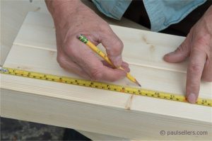
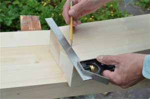
First, with all of my legs cut exactly to length, I measure up from the bottom of the leg 9” and make a mark. I place the pair of legs together, flush the ends and square the line across both legs.
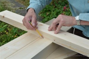
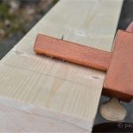
I place the cross-rail on this line and above it. This establishes the mortise width the line. I trace the position across both legs with the pencil.
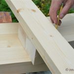
For the top rail mortise holes I place the top rail flush with the top edge of the legs and mark the width the pencil.
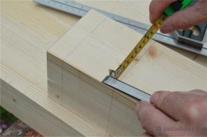
I remove the rail and then measure down from the top of the leg 1”. This is usually the width of the blade of the square: There will be a haunch at the top of the leg. This is a form of step down on the tenon that allows the full encasement of the tenon while ensuring that the tenon rail is fully held within the mortised recess by a step-down. This will be made simple shortly. I now square these lines onto the opposite faces of the legs using the square, simple.
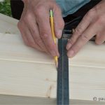
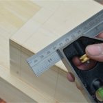
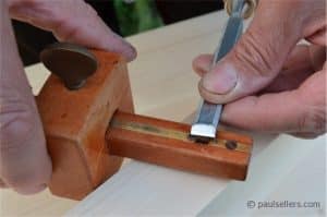
To delineate the exact width of the mortise and position it in the centre of the leg, I deduct the width of the chisel, ½”, from the width of my front leg, which measures 4”, so my remaining measurement is 3 ½”. By splitting this amount, my mortise hole is positioned centrally in the leg. Typically, we use a mortise gauge for this, I cannot assume that you have one and therefore I want to show an alternative possibility first.
In this case I am using my combination square set to 1 ¾”. I could just as easily use a rule and run the parallel line with my finger setting the distance for the pencil line. Here I am showing both the marking with the combination square and then with the mortise gauge.
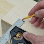
To set the mortise gauge, I first set the distance of the pin points (not the base) to the width of the chisel and then set the distance of the stock of the gauge to the first pin, centred in the leg width.
Now I can run parallel lines easily along the length between the lines.
10 Comments
Would setting long strechers in the same height of the short one, lower ones (in order to create a shelf after wards) will weaken the legs.
Thanks
If you are using the same leg size as I am, no. You might consider offsetting the leg rails on the short section to lengthen the tenons on the long one though. The bench I am making is a knock down version I wanted. I have had too many situations where I have needed to move my bench and couldn’t even get it out of the door.
The next phase in the build, after we complete the bench itself, is to retrofit with a slide in tool cupboard that has drawers and a door. By the way, my legs are about 3 3/4″ x 3 3/4″
These are timely posts. I just received your book and dvd set in the mail from Lee Valley this afternoon. There looks to be an entire dvd dedicated to this bench. I will be building this over the next few weeks.
Great. This bench is similar but different too. You might want to follow the blog and the Youtube videos we will be putting up over the next couple f weeks as these are very thorough. I have decided to make the build as genuine as possible to show people how they can develop a really fine lifetime bench even if they only have a back yard and minimal access to tools and equipment.
Hi Paul, do you by any chance have working drawings of the bench?
Thanks,
CS
Hi Paul,
I recenlty purchased my lumber for the workbench from Lowes (US). Each 2 x 4 was $2.87. Amazingly cheap.
Thank you again for the greats posts. I was wondering if were going to post instructions on how to construct the leg frame for the tail vise side?
Brandon Avakian
Hello,
Brandon, I will be posting the details for that with drawings for sizing and so on. Tenons tomorrow too all being well.
Also, hope you know that your wood is half the UK price.
I still don’t get the “why” of the haunched tenon. It looks like you could have lowered the rail an inch, used a bridle joint, or made the tenon one inch shorter. Was this a style/lesson choice or is there a real advantage I’m missing?
Paul,
I’m using 2x4s from Home Depot which have round-over edges. Do you think it’s necessary to plane the edges of the rails down to square to remove the roundover or is that unnecessary?
Comments are closed.
Privacy Notice
You must enter certain information to submit the form on this page. We take the handling of personal information seriously and appreciate your trust in us. Our Privacy Policy sets out important information about us and how we use and protect your personal data and it also explains your legal rights in respect of it. Please click here to read it before you provide any information on this form.
Would setting long strechers in the same height of the short one, lower ones (in order to create a shelf after wards) will weaken the legs.
Thanks
If you are using the same leg size as I am, no. You might consider offsetting the leg rails on the short section to lengthen the tenons on the long one though. The bench I am making is a knock down version I wanted. I have had too many situations where I have needed to move my bench and couldn’t even get it out of the door.
The next phase in the build, after we complete the bench itself, is to retrofit with a slide in tool cupboard that has drawers and a door. By the way, my legs are about 3 3/4″ x 3 3/4″
These are timely posts. I just received your book and dvd set in the mail from Lee Valley this afternoon. There looks to be an entire dvd dedicated to this bench. I will be building this over the next few weeks.
Great. This bench is similar but different too. You might want to follow the blog and the Youtube videos we will be putting up over the next couple f weeks as these are very thorough. I have decided to make the build as genuine as possible to show people how they can develop a really fine lifetime bench even if they only have a back yard and minimal access to tools and equipment.
Hi Paul, do you by any chance have working drawings of the bench?
Thanks,
CS
Hi Paul,
I recenlty purchased my lumber for the workbench from Lowes (US). Each 2 x 4 was $2.87. Amazingly cheap.
Thank you again for the greats posts. I was wondering if were going to post instructions on how to construct the leg frame for the tail vise side?
Brandon Avakian
Hello,
Brandon, I will be posting the details for that with drawings for sizing and so on. Tenons tomorrow too all being well.
Also, hope you know that your wood is half the UK price.
I still don’t get the “why” of the haunched tenon. It looks like you could have lowered the rail an inch, used a bridle joint, or made the tenon one inch shorter. Was this a style/lesson choice or is there a real advantage I’m missing?
Paul,
I’m using 2x4s from Home Depot which have round-over edges. Do you think it’s necessary to plane the edges of the rails down to square to remove the roundover or is that unnecessary?