Making the Router Plane Body
Making the Base
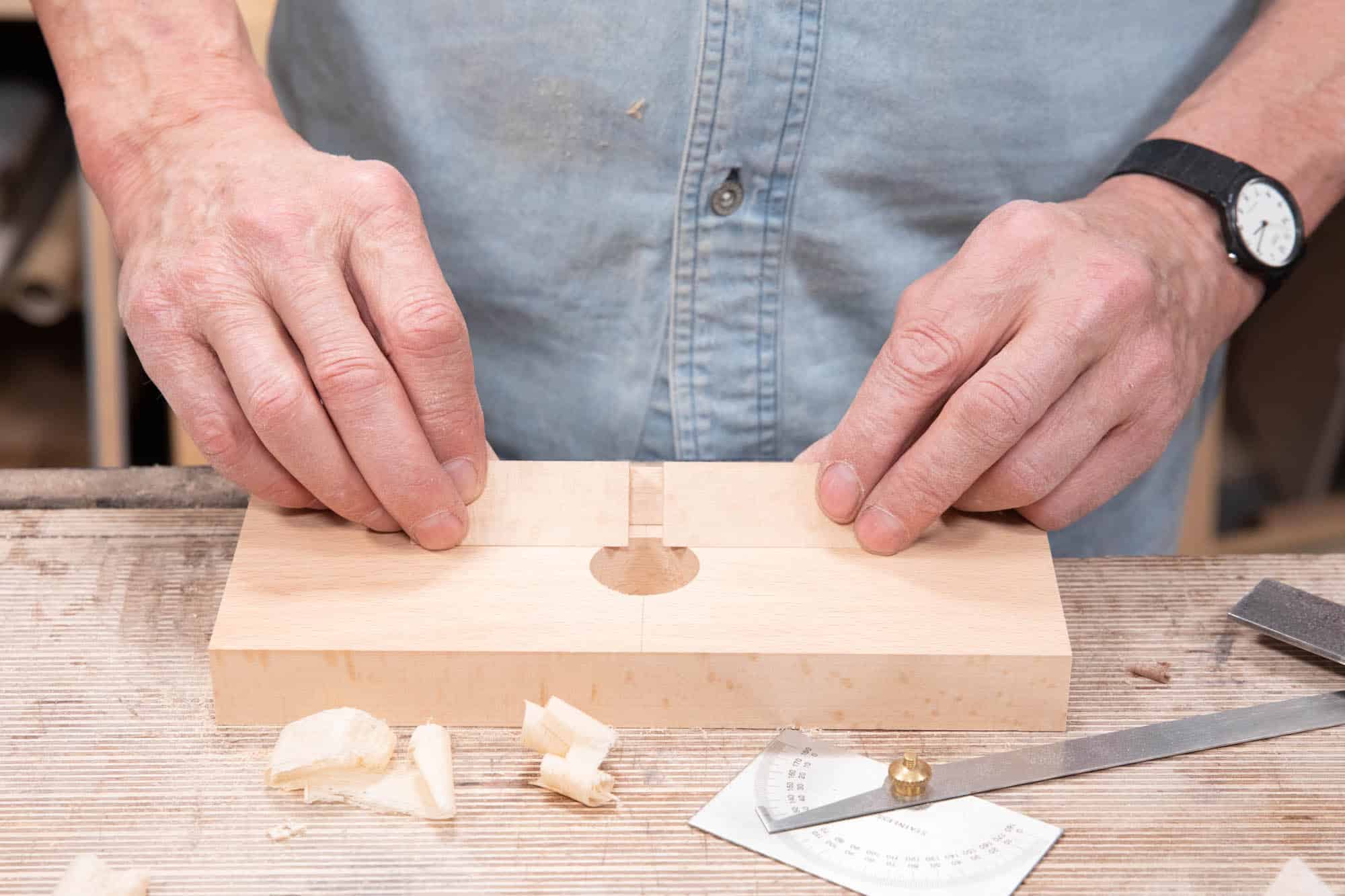
The blank dimensions for the base of the plane are 9 1/2″ (241mm) by 3 3/4″ (95mm) by 1″ (25mm). Start by choosing your preferred orientation and make the corresponding markings.
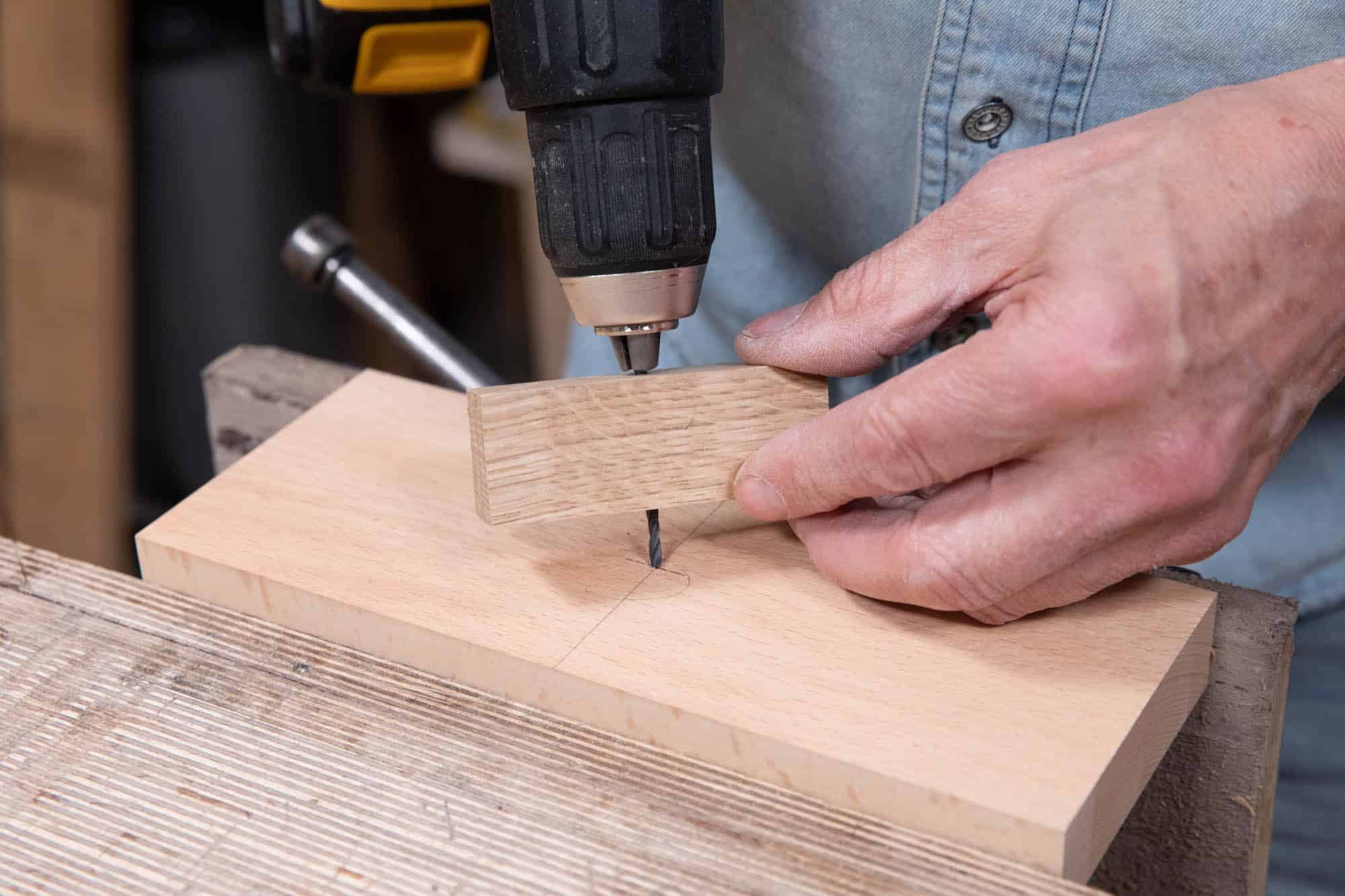
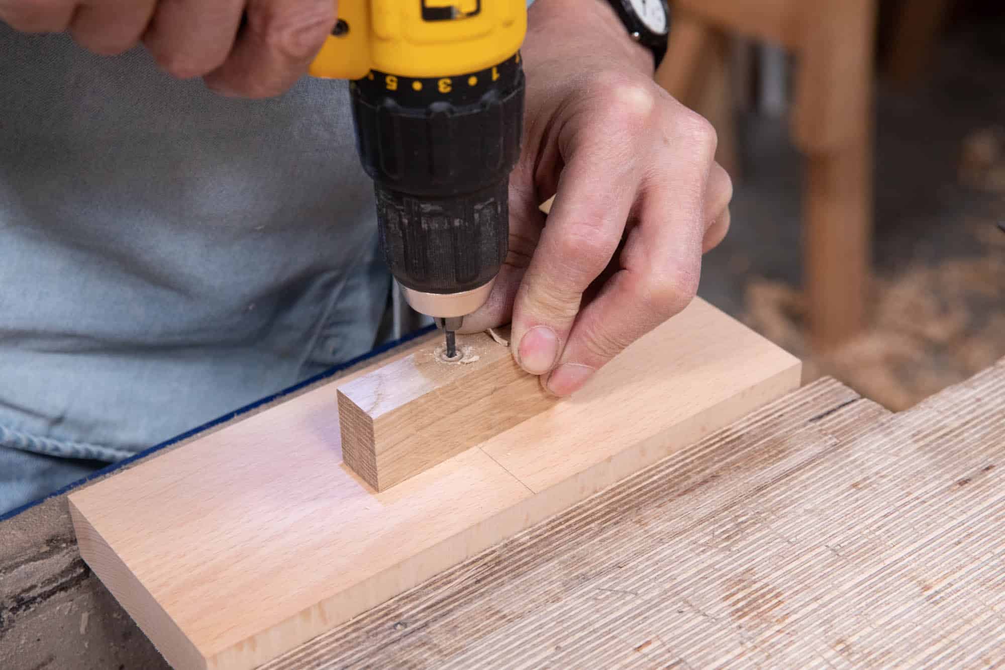
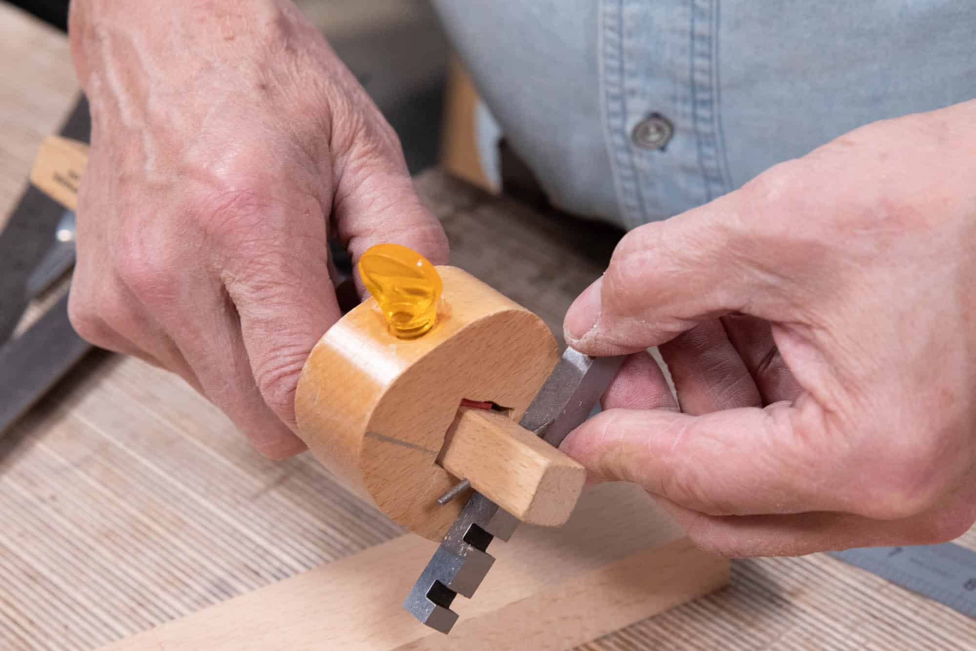
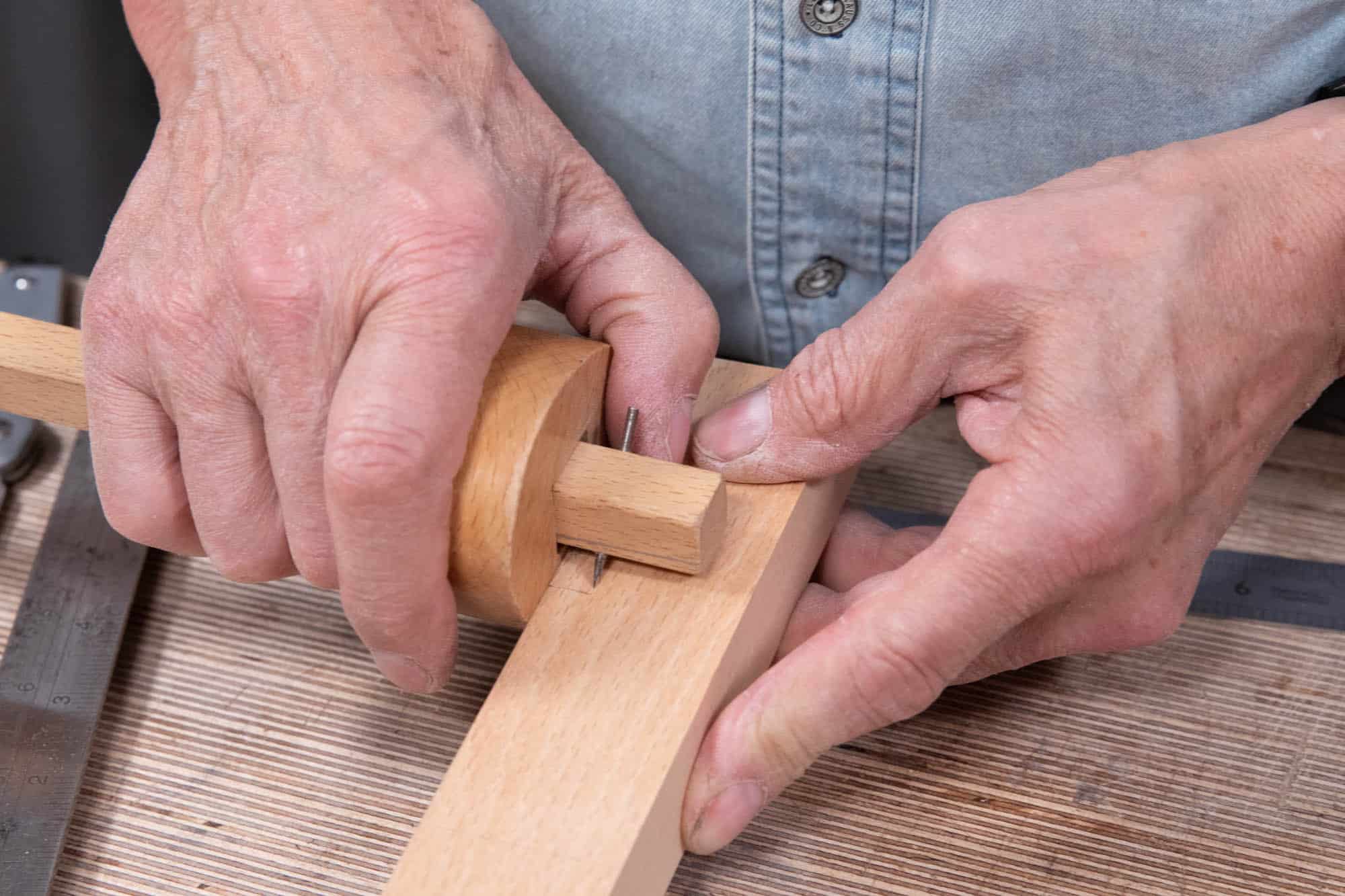
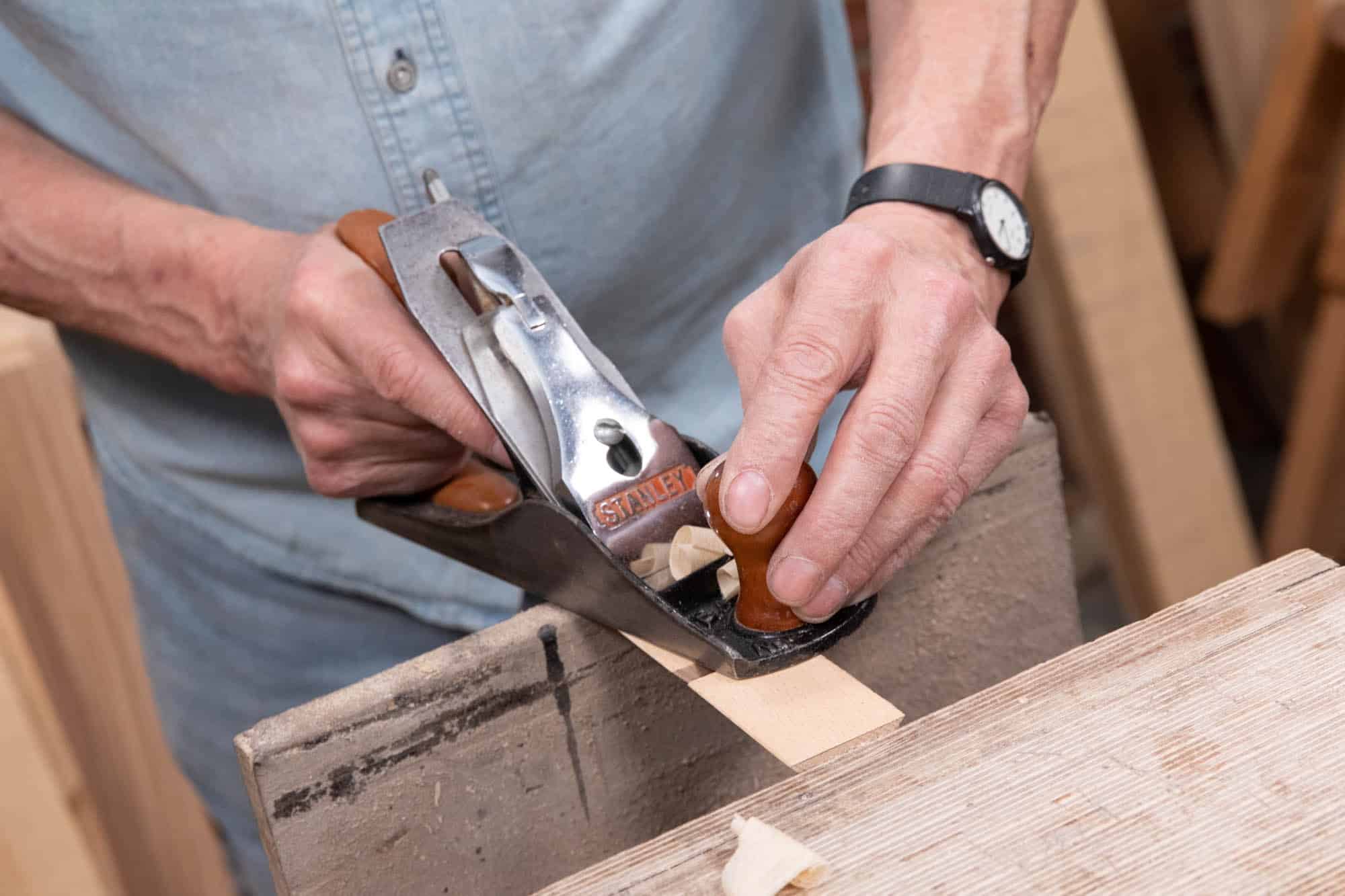
Drilling pilot holes perpendicular to any surface freehand is difficult if you want to get consistently accurate results. In the case of this router plane, accuracy is important for the anchor bolts which hold the handles, secure the retainer bar and keep the depth adjustment mechanism steady and in-line with the blade. Using an accurately made pilot hole guide ensures squareness to the surfaces which in turn means that all of the components relying on the anchor bolts turn and adjust correctly and maintain parallel movement throughout. Click below for a detailed post on making a drill bit guide.
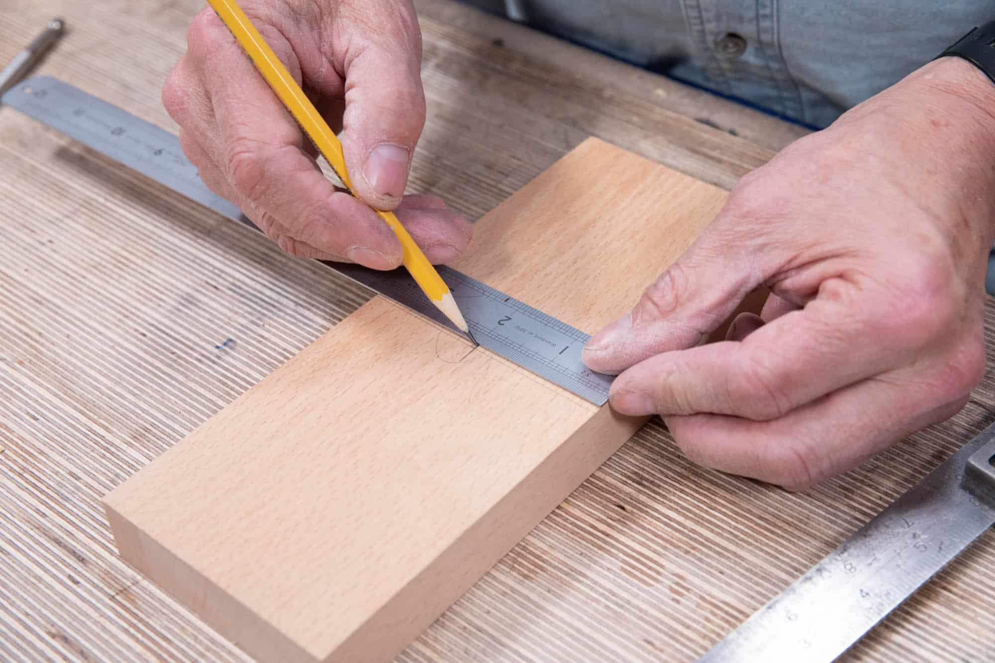
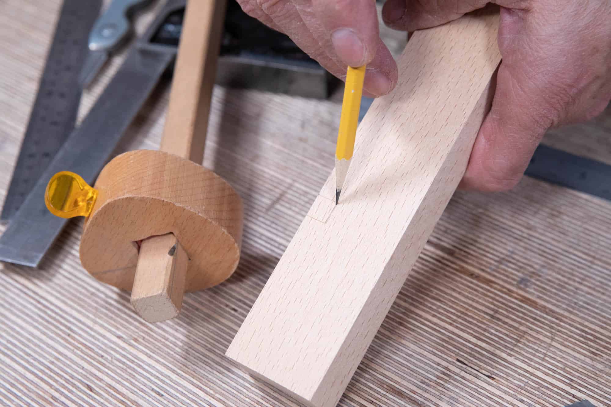
Find the midpoint across the length and then measure 2″ (51mm) from the back edge of the blank. Mark the points where the two lines cross.
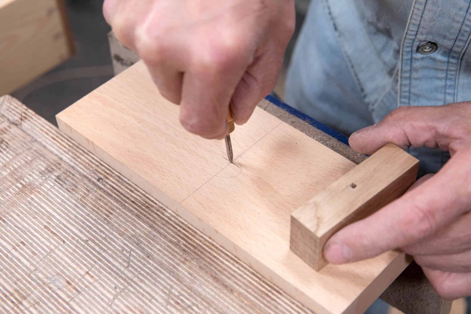
Then, use a sharp, pointed square awl to ream out a clear start point for the pilot hole.
Use your guide block and press it firmly to the main blank and drill into and through the wood. This hole will guide a flat bit or auger bit.
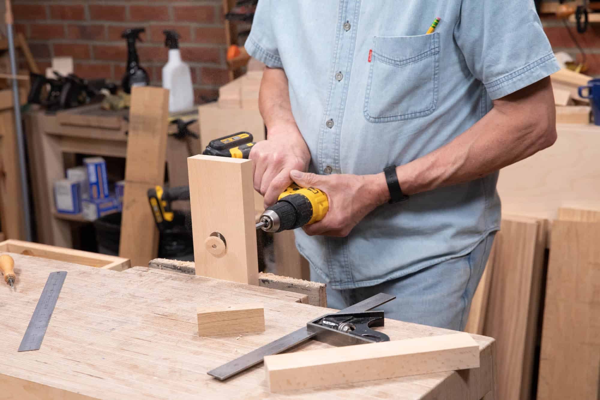
With the pilot hole drilled, clamp your blank vertically in the vise, as you will need to apply significant pressure, and bore a 1 1/4″ (32mm) hole, stopping about half way through.
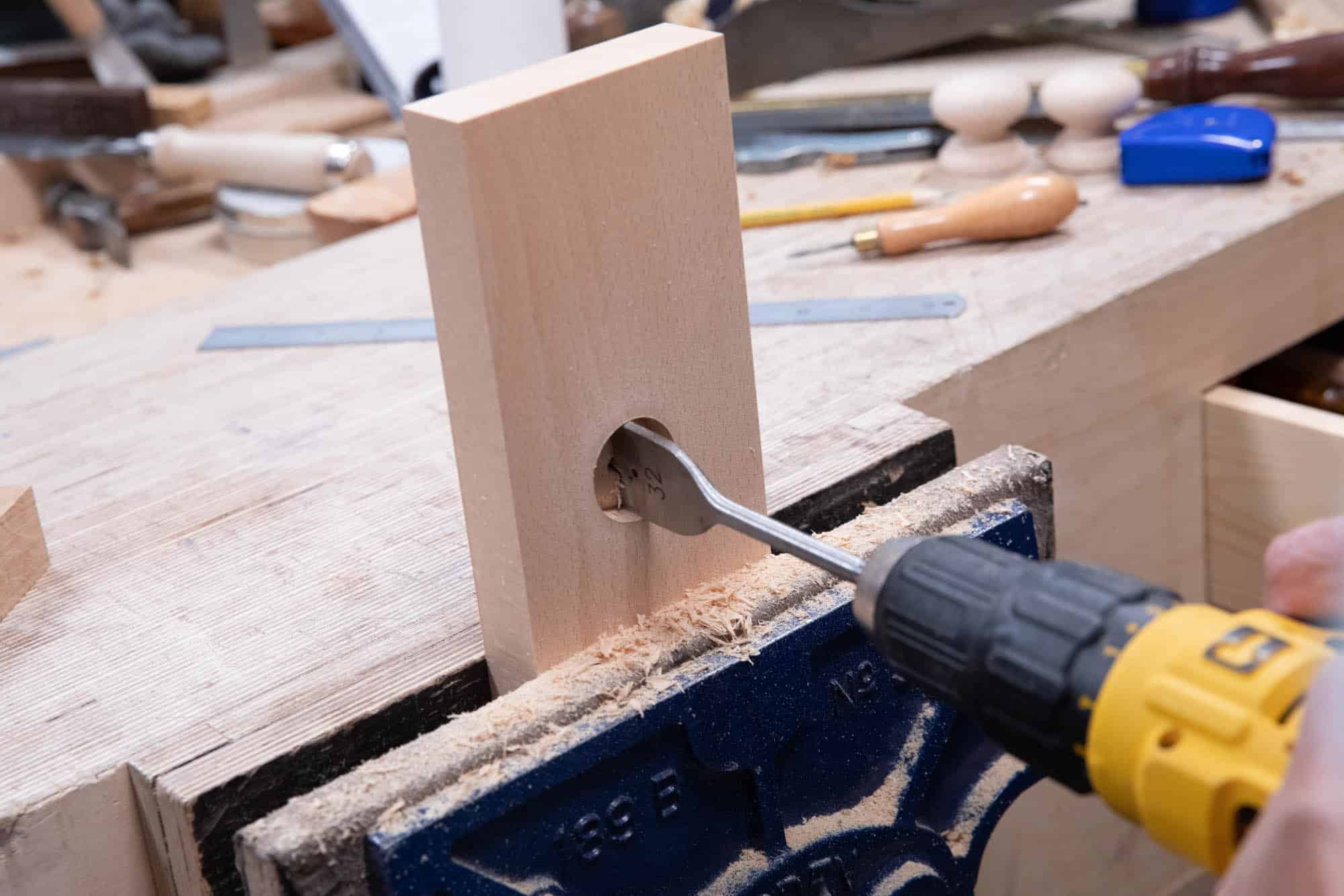
Turn around to finish the hole from the other side to get a clean, crisp ridge on the opposite face. Alternatively, clamp a sacrificial piece on the back of the blank with the two surfaces flat against each other with no gaps and then you can drill through all the way from one side.
Laying Out the Recess
The blank for the upstand measures 9″ x 1 1/2″ x 1″ (229mm x 38mm x 25mm). We have allowed extra length on the blank to facilitate handling and clamping, as the final length will be 5 1/2″ (140mm).
This section houses the blade at an inclined position and also the anchor bolts for the retainer bar and the adjustment mechanism. Starting with a trued blank allows us to cut the recess square to the sides before ripping down the length to get the 50° bedding angle. Doing it this way means you will need to start with a with the 1″ (25mm) blank but once you cut the upstand off the main block at an angle at the final height will be 3/4″ (19mm).
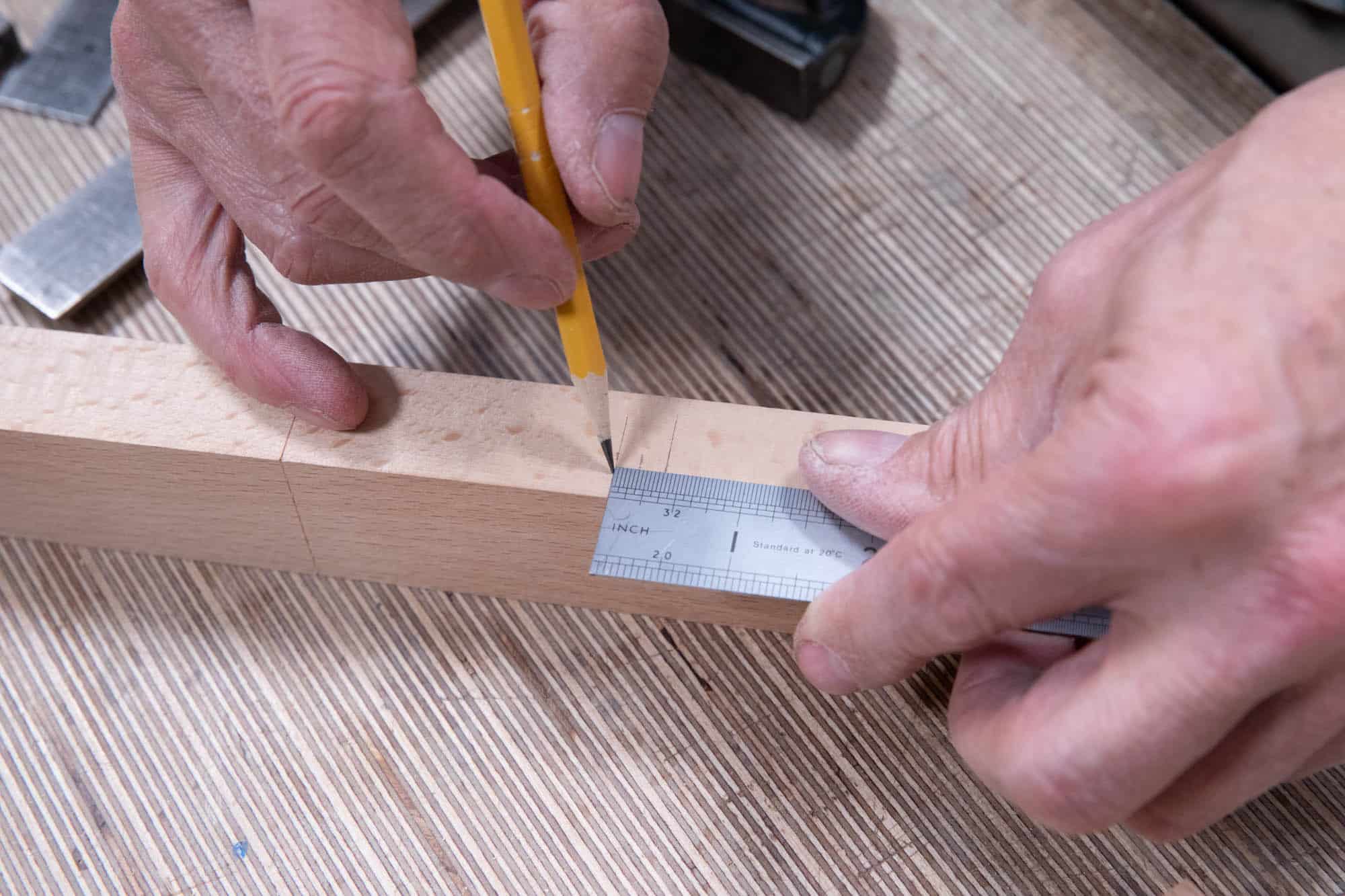
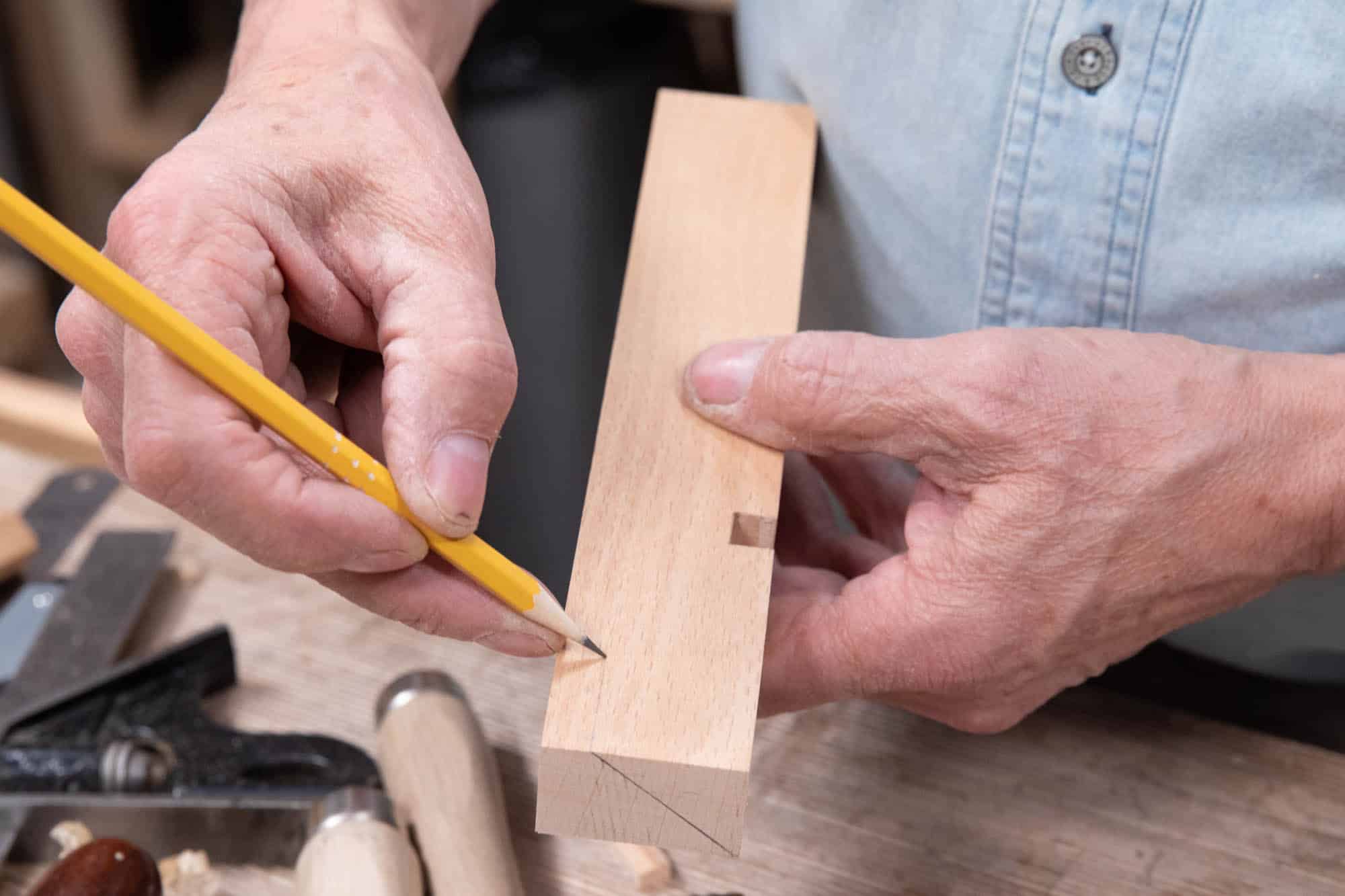
First, on the edge of the blank, measure 2 3/4″ (70mm) from one end and then mark half the width of your blade (in my case 5mm) to either side with a sharp, pointed pencil. (If you are making the blade yourself, use the steel stock to get the exact width. Alternatively, you can make the blade beforehand. Watch Paul making a blade here.)
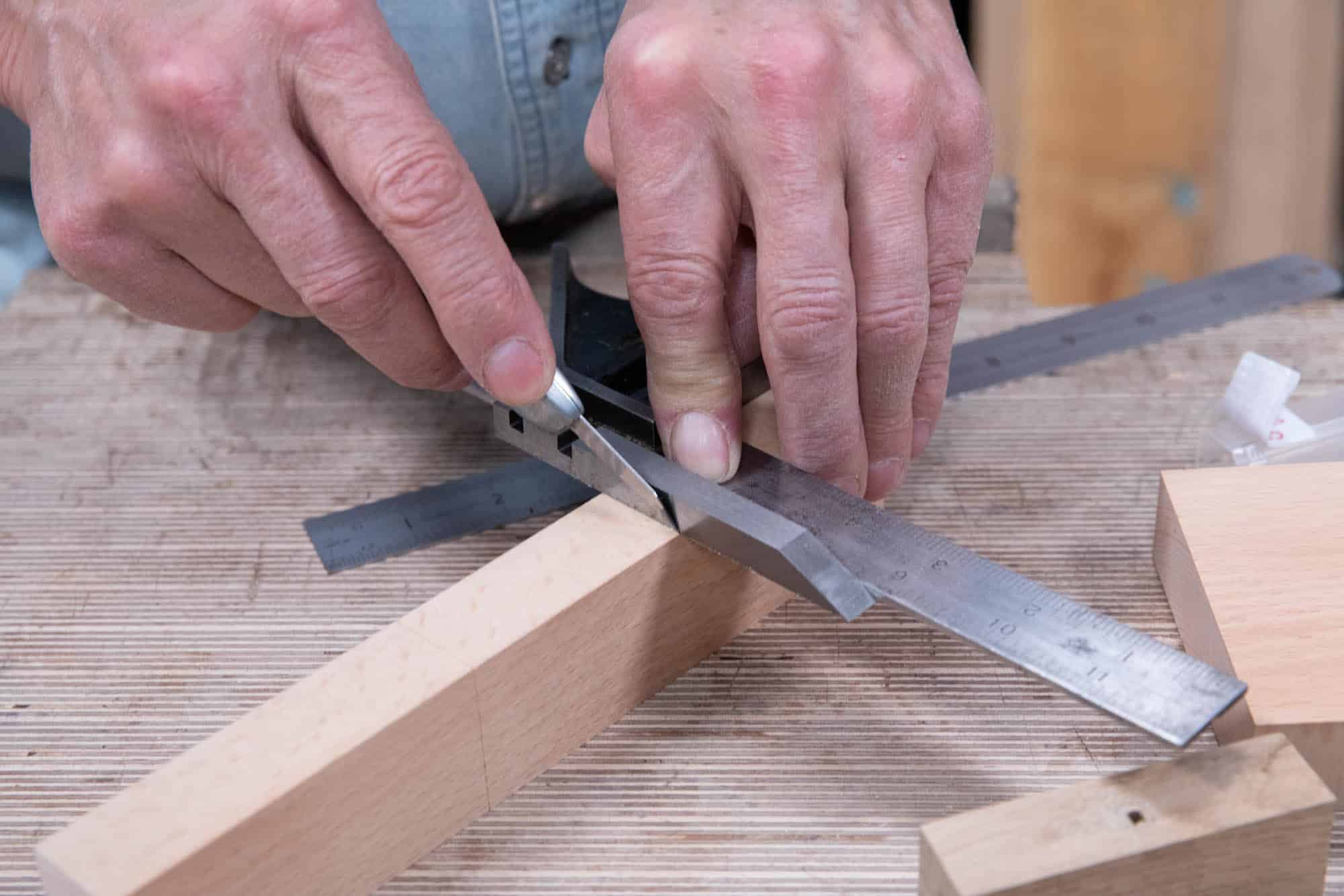
You can now define the first wall by squaring a knifewall across with a square. Next, using the cutting iron for exactness, make the second knifewall parallel to the first.
Extend both knifewalls just shy of the thickness of the blade (in my case I went 9mm for a 10mm blade) onto the top and bottom faces.
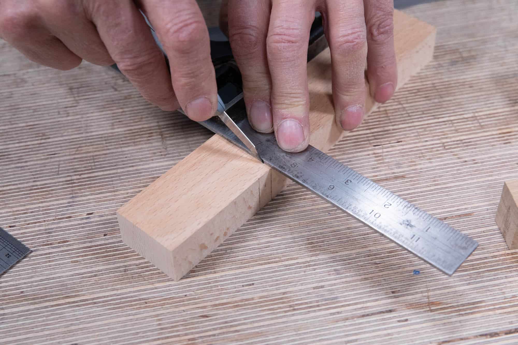
For the exact depth of the recess, set a marking gauge to the thickness of the cutting iron minus 1mm (around 1/32″). With this setting, run your gauge between the two knifewalls on both ends of the recess.
Cutting the Recess
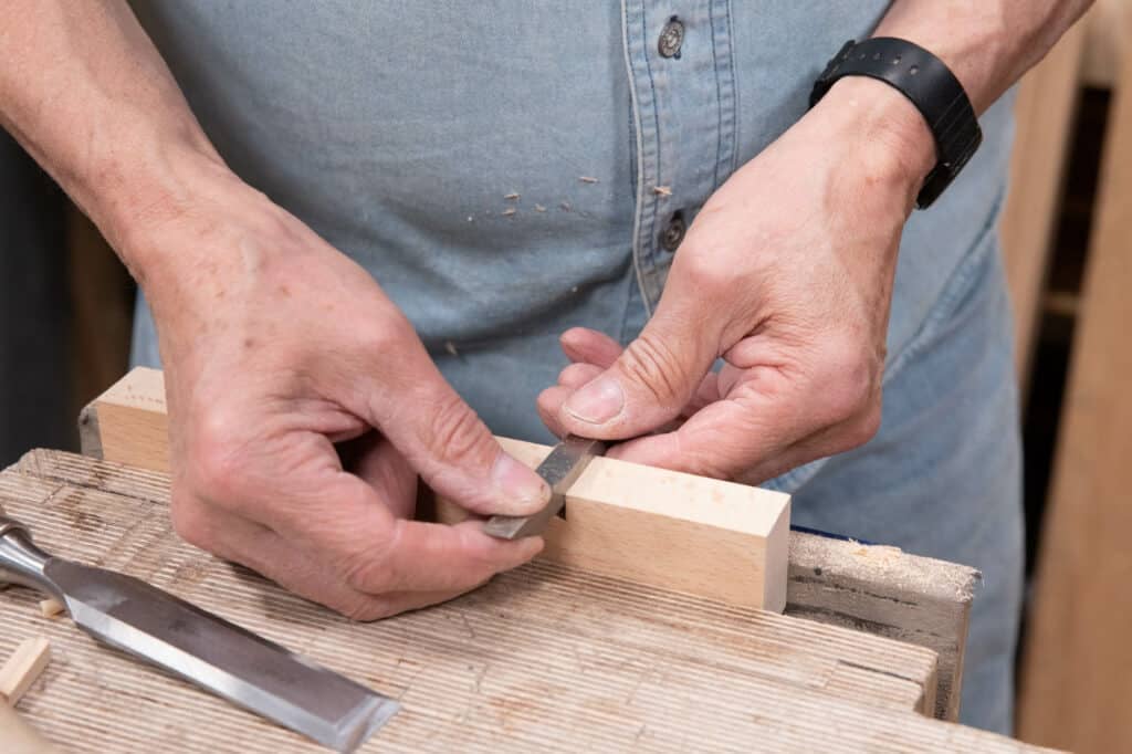
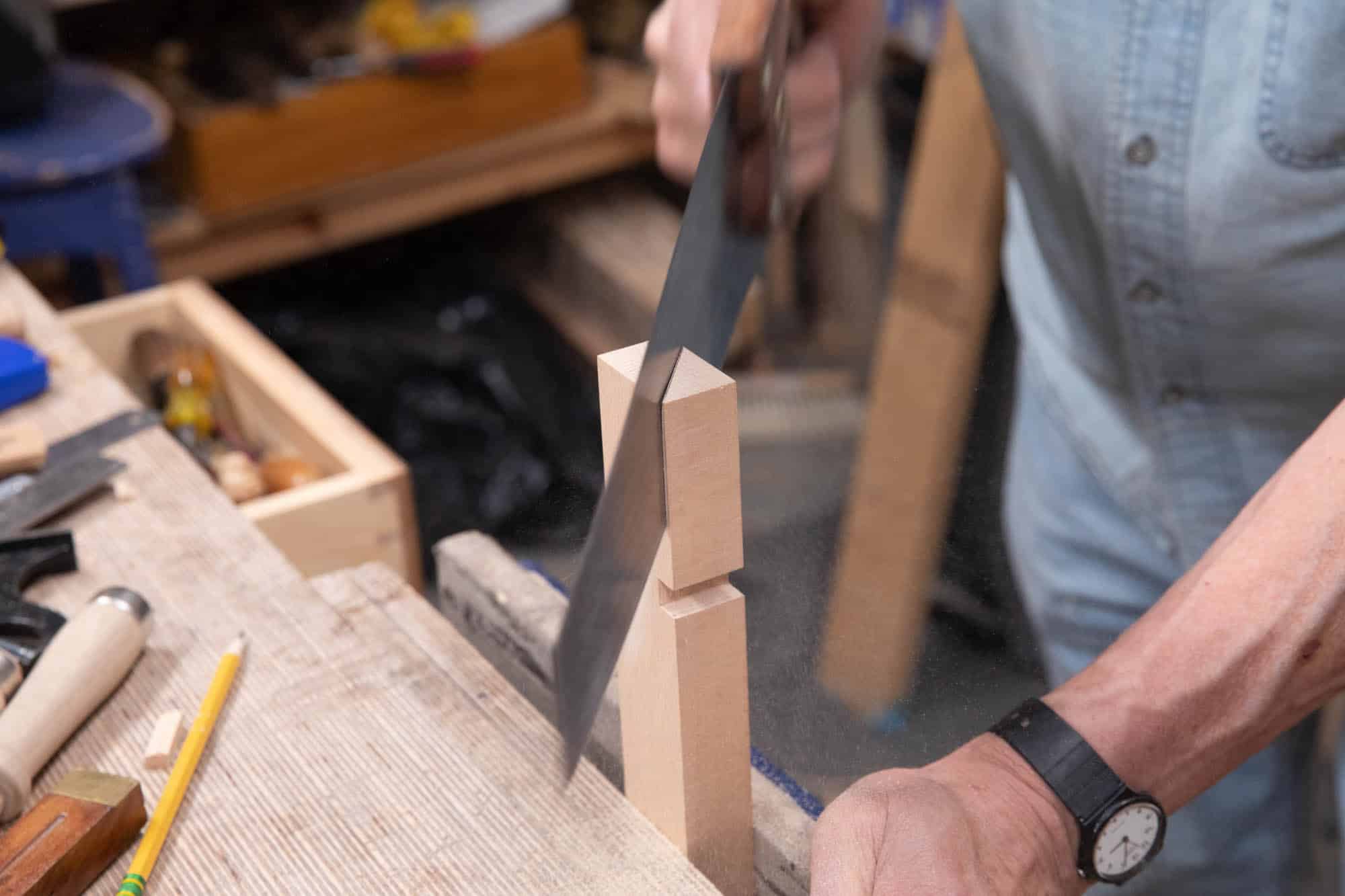
Saw down both knifewalls on the waste side of the lines taking care to stay close to and within the knifewalls.
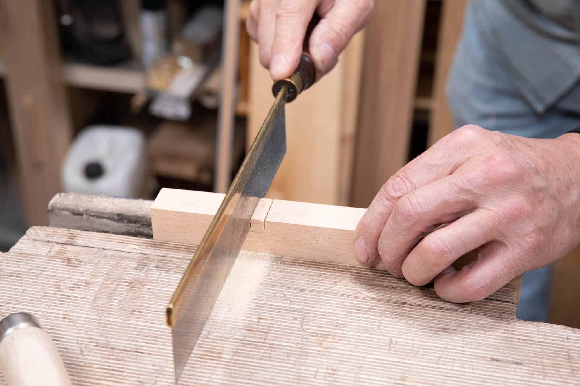
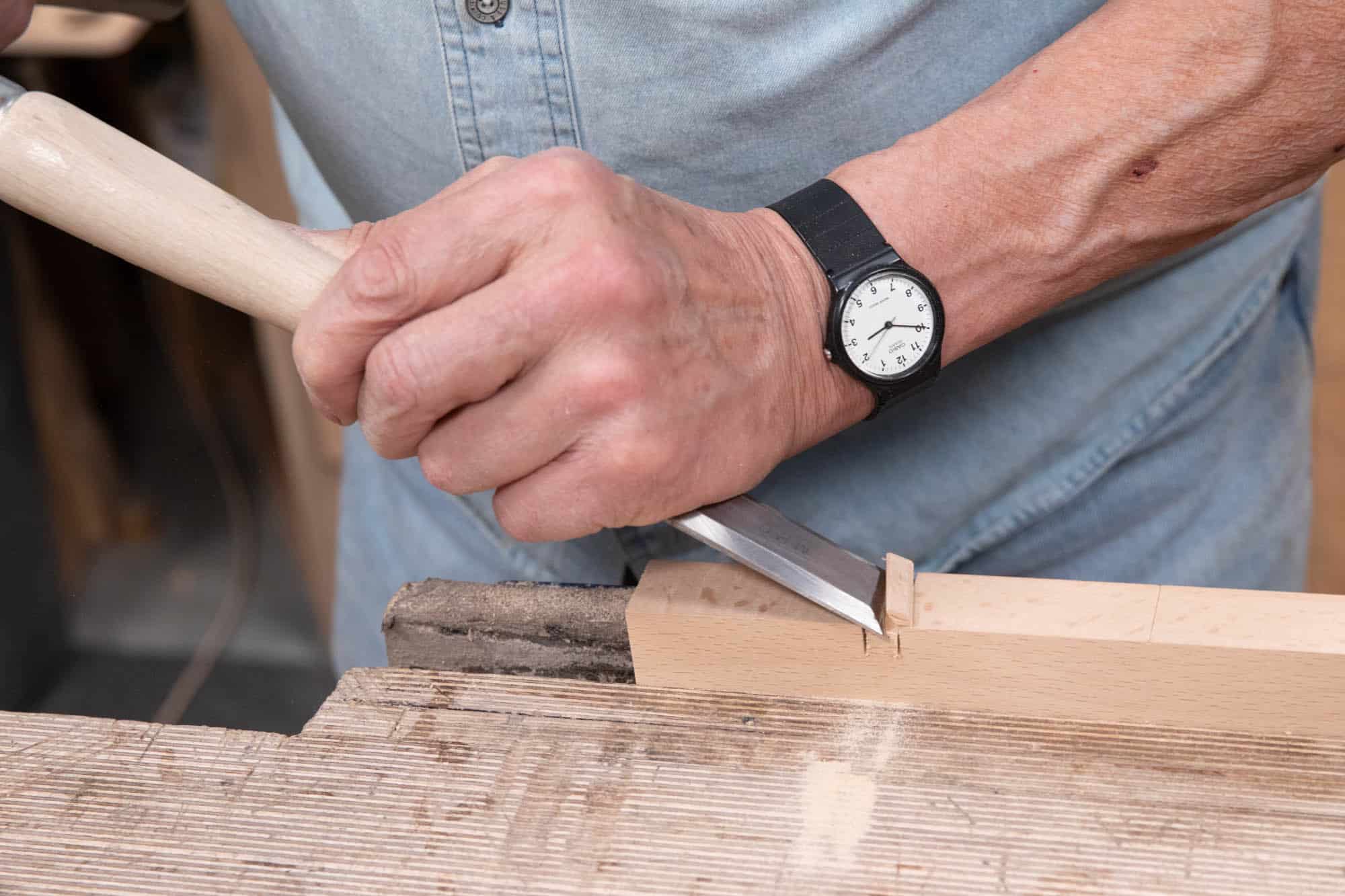
Splitting off the bulk of the waste will make it easier to pare out the waste wood with the narrower chisel across the grain.
Note: Recessing the cutting iron is an important step. You want the recess to be sized exactly and preferably not loose or uneven in any way. Take your time and sharpen the tools as necessary. Accuracy is everything.
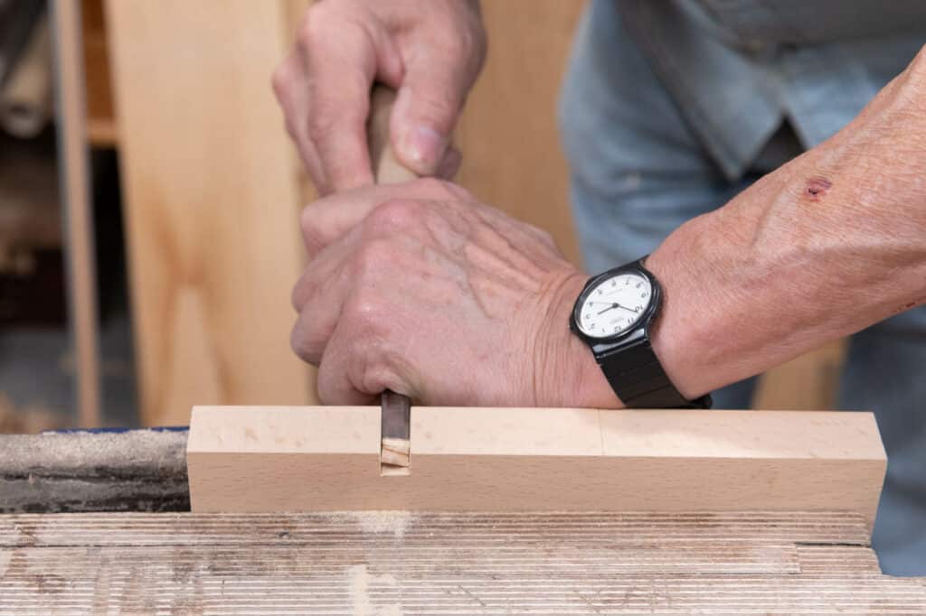
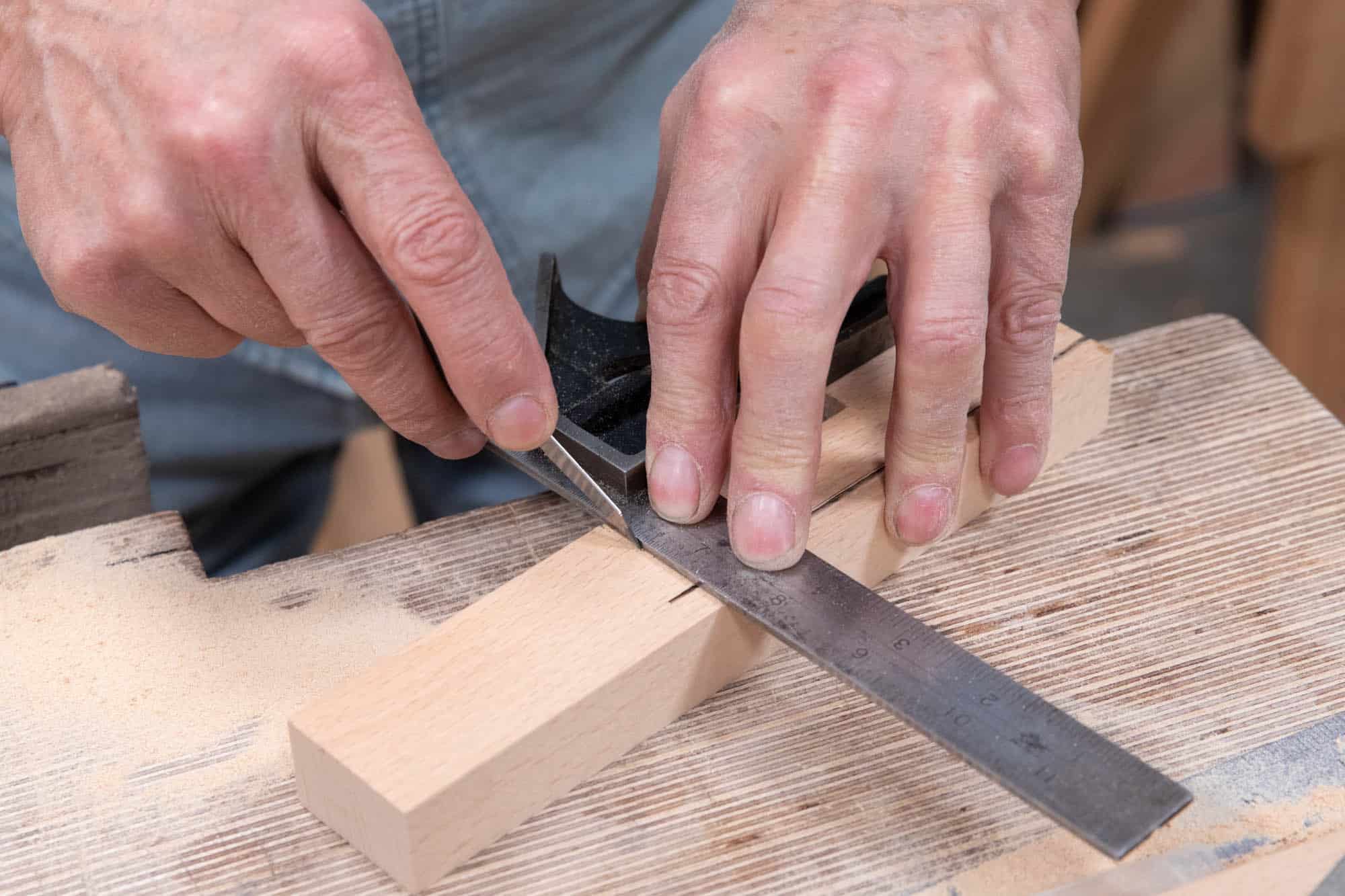
With the bulk removed, pare across the surface grain carefully to the gauge line taking care to remain parallel and accurately to the lines on both sides. Also, clean up any unevenness left by the saw kerf on the walls.
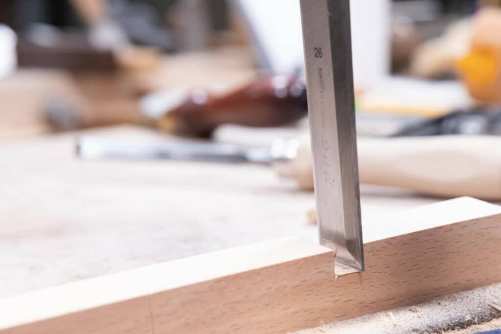
Check the depth by inserting the cutter and holding a straightedge on the surface. The cutter should protrude above the surface of the upstand by around 1mm (~1/32″).
Laying Out the Bedding Angle
The next step is to cut the angle on the underside of the upstand that will adjoin the main body or sole piece of the plane. We use a protractor set to 50°, place the trammel beam to the bottom front corner of the blank, registering on the face where the recess is laid out, and strike a line to the angle as shown.
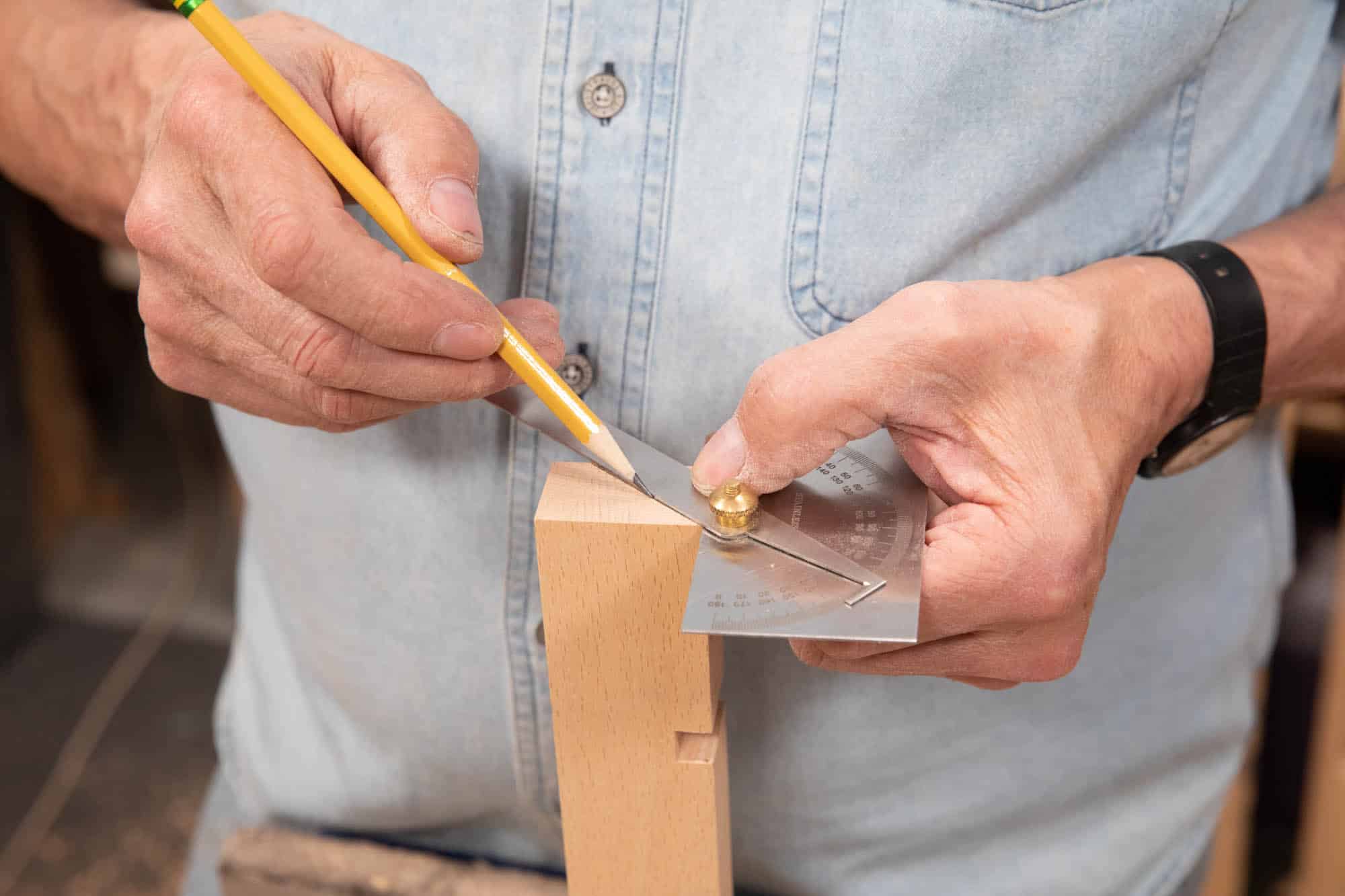
Where the line hits the back edge, run a parallel line along the length to guide your saw cutting. You can use a marking gauge or a combination square to ensure paralellity if you so wish.
Ripping and Planing the Underside of the Upstand
Cutting the upstand from the blank and truing up is quite straightforward one you have the layout lines to work to. Again, it is best to take your time and correct any misalignments with the saw as early as possible. Cutting slightly away from the line allows for truing up with a plane without loosing your references and therefore maintaining the 50° bedding angle.
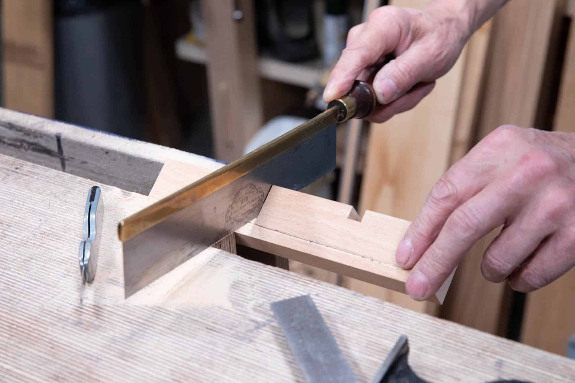
With your blank clamped upright in the vise, start ripping along the length, making sure to stay square and marginally away from both the line and the opposite front corner.
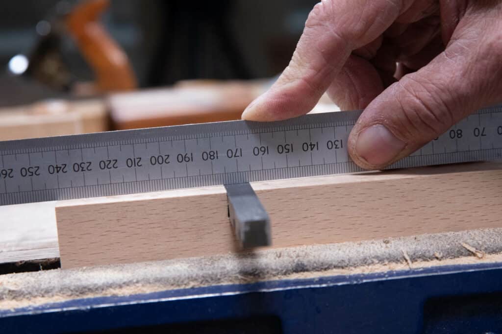
At the 5 1/2″ (140mm) mark, stop sawing and square a knifewall on both faces and then cross-cut with a small tenon saw.
It is easier to plane the underside of the upstand if it is clamped perpendicular to the vise jaws as this allows for positive clamping and you can work towards the bench. Check the meeting face for mating to the base of the plane.
Position the upstand onto the base to make sure everything lines up and looks symmetrical.